> For the complete documentation index, see [llms.txt](https://docs.overthereality.ai/over-sdk-manual/llms.txt). Markdown versions of documentation pages are available by appending `.md` to page URLs; this page is available as [Markdown](https://docs.overthereality.ai/over-sdk-manual/over-visual-scripting-legacy/visual-scripting-essentials/overnode.md).

# OverNode

### Description

The OverNode is the foundation of the Visual Scripting system: responsible for the implementation of a specific functionality, in order to be used to create more complex logic.

An OverNode is responsible for a single function within the execution flow.&#x20;

#### Execution

Each node is tied to another and is created with a set of Ports, whose goal is to carry on the information (tied to a specific data type).&#x20;

There are several types of Ports involved:

<table><thead><tr><th width="205.7659040188865">Name</th><th width="340.1572968009442">Description</th></tr></thead><tbody><tr><td>Input</td><td>Port used to input information into the node.</td></tr><tr><td>Output</td><td>Port used to output information, processed by the node, to the next node.</td></tr><tr><td>Flow</td><td>Port used to carry on the execution flow, it outputs a specific kind of information</td></tr></tbody></table>

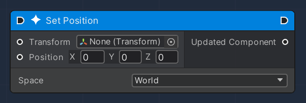
<figure><img src="/files/CBxIrasOmE3pnarOqSI9" alt=""><figcaption><p>Input ports are shown in the left side, output ports in the right side. <br>Flow ports are represented by an arrow-like port inside the node header.</p></figcaption></figure>

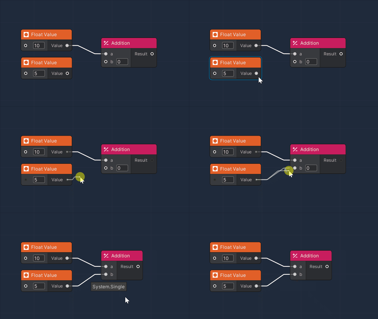
A node can be connected by clicking an output port. This will create a new Edge, to be dragged and dropped to the input port of the next node.&#x20;

{% hint style="info" %}
**Note**: in order for a Connection between ports to be established there must be compatibility between the ports. While dragging an Edge, in order to simplify the process, the non-compatible end ports will be turned off visually, thus becoming non-interactive.
{% endhint %}

<figure><img src="/files/FLJ7R0jrkBH195nnf8Kq" alt=""><figcaption><p>Example of Edge creation</p></figcaption></figure>

The OverNodes can be classified into two categories:

* **Flow Nodes:** provided with Flow Ports, they are used to link the node directly to the Unity runtime execution flow and propagate it further to the following nodes
* **Plain Nodes:** these don't possess Flow Ports, so they can't directly access the execution flow. Instead, they deliver the information "on-demand" (i.e. it processes the information only when another node, tied to it, asks it to).

#### Visual Representation

Each node inside a graph is represented by a small panel, with a Header part (to the top) and a Body.

The Header contains the following information:

<table><thead><tr><th width="205.7659040188865">Name</th><th width="340.1572968009442">Description</th></tr></thead><tbody><tr><td>Icon</td><td>The Image that represents the type of the component, manipulated by the node</td></tr><tr><td>Title</td><td>The name of the node involved, each title by itself provides hints to the user about the node's functionality</td></tr><tr><td>Flow Ports</td><td>If the node is used to build an execution flow, an input/output port is shown</td></tr></tbody></table>

The Body of a node serves as a container for the Input (shown in the left side of the node) and the Output (right side) Ports. Each port is defined by a name and the associated data type.

In addition, a node can contain a certain number of editable fields, to further customize its behaviour.

<figure><img src="/files/CBxIrasOmE3pnarOqSI9" alt=""><figcaption><p>Example of an OverNode</p></figcaption></figure>